Kikimora
An ESP8266-based systems monitoring device

Kikimora was born form an idea given to me by colleague at work. The idea was to create a simple device, which with the aid of two LEDs would indicate if a computer system is up or down. The device could be set on top of any computer screen in order to make it easy to check out.
I specified further what I would try to accomplish and thought of the following: The device would be configured to ping or somehow GET a webpage every X seconds. If the page responded with a 200 HTTP code, let’s light the green LED, any other message: red LED.
After that I added some requirements to the device: to make it self-contained, as simple as possible to use, and small (in that order). So, I started the hunt for an arduino-like platform with embedded WiFi capabilities, and landed on the ESP8266 module family. I bought an ESP8266-01 and ESP8266-12E, because they are dirty cheap. I ended up using the 01, the reason is simple, I liked the restrictions imposed upon me by using such a “simple” device. It only offered me a WiFi link and 2 GPIO ports (though I’m sure someone has already invented some kind of hack to use the RX/TX ports for GPIO).
PROGRAMMING
After a long afternoon programming the ESP8266 I managed to cram a program which did the following:
- Setup a Wifi connection to a hardcoded network
- Setup an internal timer (based on the OSs functionality, and not some cheesy software hack)
- Host a configuration page to setup the page to monitor
- Write some code to light a LED or the other based on the target website’s status
I took into account the hardware limitations and avoided to work too long in the device’s main (and only?) thread.
The code is available in the project’s repo, linked at the start of this article.
ELECTRONICS
The electronics were pretty basic, in the end it’s just a microcontroller and two LEDs. In order to pursue the “simplicity” aspect of the project I wanted to supply the juice via an USB port, like most handheld devices around us. Two problems arise: 1. A micro-usb port is probably fragile + difficult to solder in a perfboard. 2. USB provides 5V… and the ESP8266 needs 3.3V.
The first one I solved using and old-school USB-A female port. To solve the second one I wanted to get away with a voltage divider, but due to the laws of electronics it wound up to be a difficult task, so I summoned all my patience, order a bunch of voltage regulators on ebay and put the project on hold for a week. When they arrived everything worked perfectly.
The schematic for the circuit is as follows:
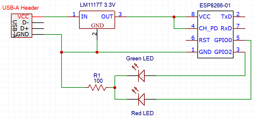
First, sorry for putting an ESP8266 which is the wrong module in the schematic, but I didn’t find the 01… Secondly, there is no much mystery to it. The resistor after the LEDs should avoid the build up of “infinite” current, and that’s all.
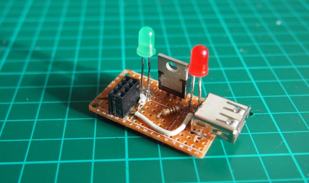
The first prototypes I tried out in the proverbial protoboard. The definitive circuit was build on a perfboard. Pretty badly. I should get a better soldering iron and something to hold the board and components while I solder them. Sorry for the terrible craftsmanship you’ll see in the photos.
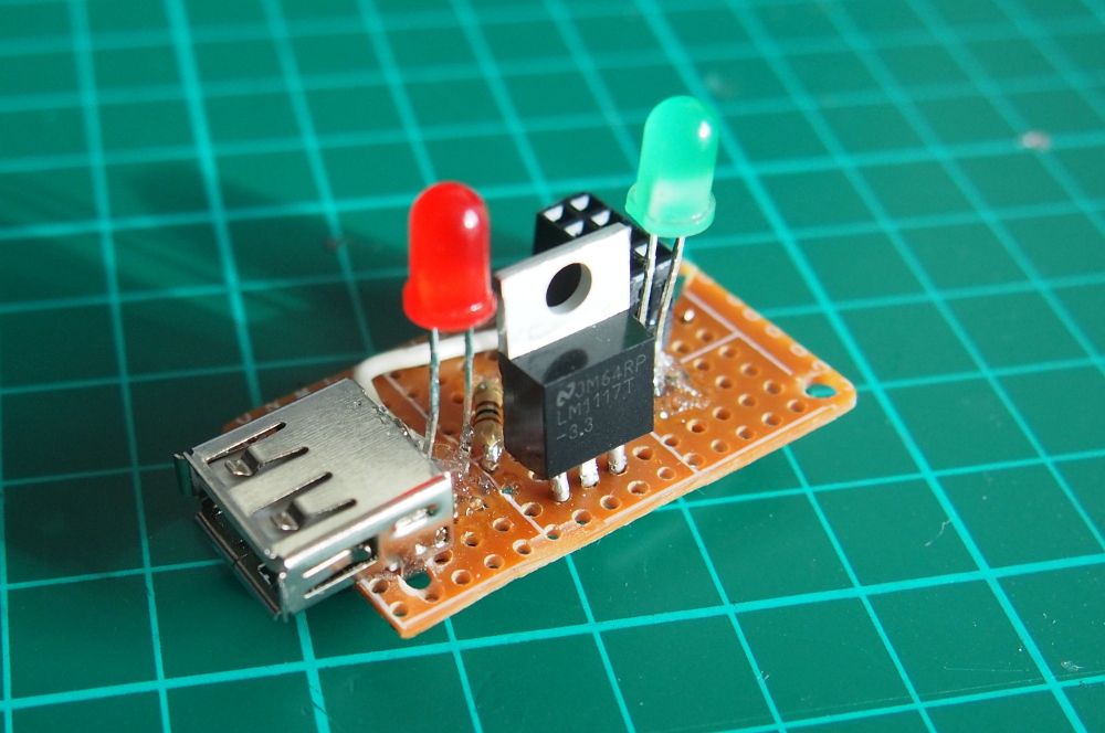
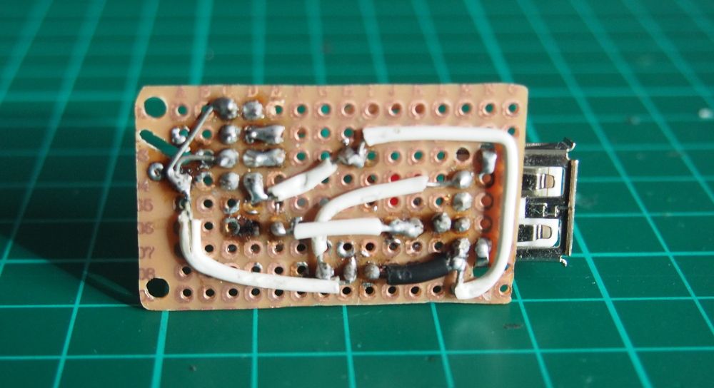
There are two more things I would like to talk about: First the operating voltage. As you have probably notices there is a voltage regulator which reduces the USB’s 5V to 3.3V for the ESP8266. The bad thing about this is that the LEDs will be slightly underpowered, emitting only a very faint light.
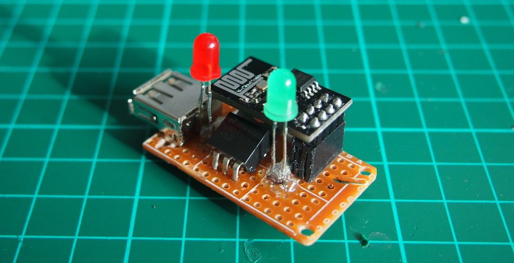
Secondly, the ESP8266 is mounted on some pins and not directly soldered to the perfboard. This is so in order to make it easier to reprogram the microchip in the future without much hassle. The downside: The high occupied by the whole ensemble, which is quite a lot for a device of this size.
EXTERIOR
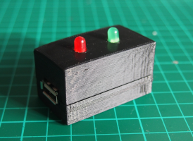
The exterior is a simple parallelepiped or a rectangle with volume. I made it so that I could be easily opened in the middle and accommodate all the components (mainly regarding height).
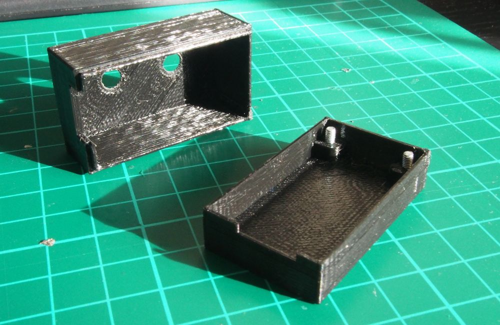
The bottom part of the case takes the board. The perfboard is mounted on two screws and the edge of the case, leaving a bit of space beneath for some cables and solder blobs. The top was build with the height constraints in mind. There are two holes for the LEDs to go through, and a notch for the upper half of the USB port.
I designed the case in FreeCAD (in a pretty unorthodox way, regarding good practices). The top half was a bit of trial and error thing, it was difficult to define the right height for the piece and LED hole diameter, taking into account my printer’s tolerances and accuracy error.
I exported the models to STL meshes and converted them to gcode using Cura 15. Then I printed the case in my Prusa i3-model 3D-printer in PLA plastic.
PUTTING IT TOGETHER
To finish it of I glued the LEDs to the perfboard with some silicone sealant and decided to bend the voltage regulator beneath the ESP8266 board in order to avoid it hitting the top of the case. As it doesn’t heat up too much I think it won’t cause a problem there.
You've seen the complete build on the beginning of this article:
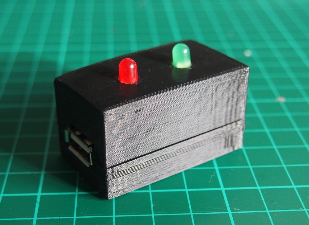
The ESP8266’s code, CAD and STL models are all open source. You can find a link to the repo.